Overview
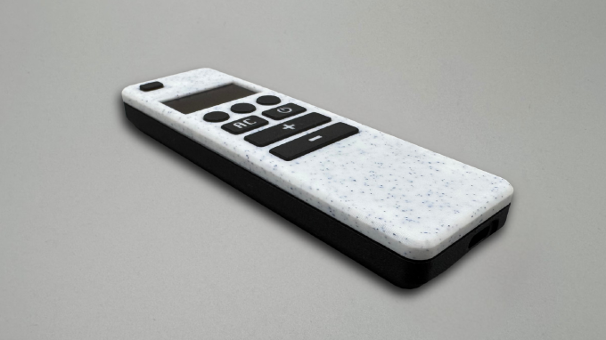
This guide walks you through the full assembly process of the Smart OLED Remote.
The process is divided into three main stages:
- preparing and soldering all electronic components
- assembling the enclosure and fitting all parts together
- powering the device for the first time and verifying everything works
Follow the steps in order to ensure proper fit, alignment, and reliable operation.
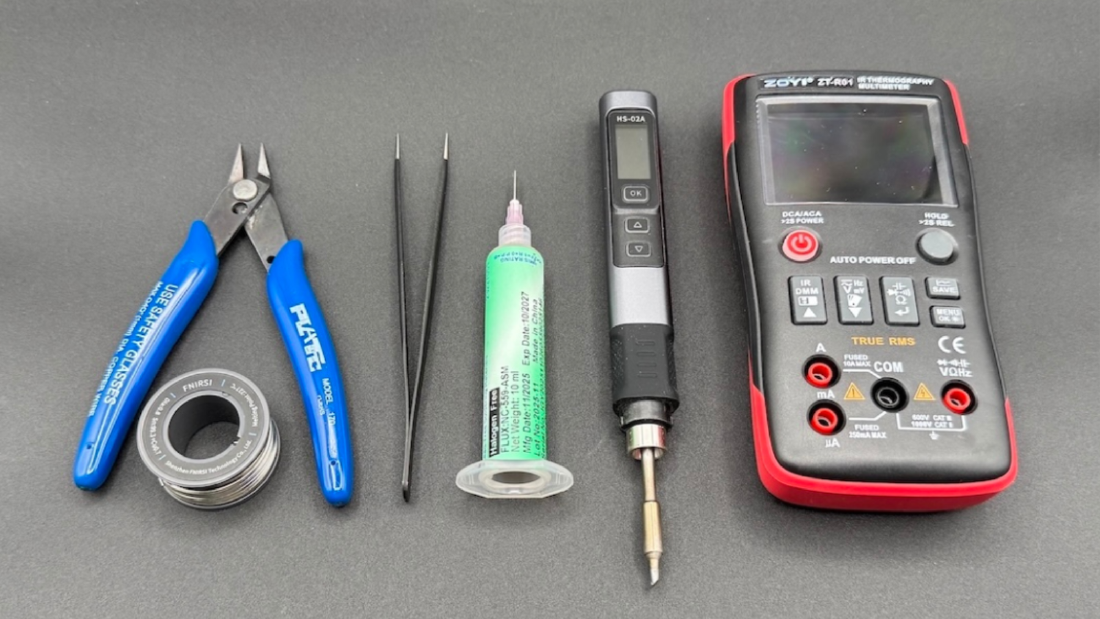
Tools Required
- Soldering iron
- Third hand or clamps
- Tweezers
- Flush cutters
- Flux (recommended)
Bill of Materials
| Part Symbol | Description | Qty |
|---|---|---|
| PCB | Custom designed PCB | x1 |
| ESP32_DEVKIT_LOLIN_V1 | WEMOS Lolin32 V1.0 | x1 |
| OLED_SH1106_I2C_128x64 | OLED Display 1.3" | x1 |
| BAT_1200MAH_JST_1P25 | LiPo 1200 mAh battery with JST 1.25 mm connector | x1 |
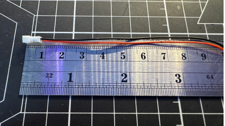
| JST 1.25 2P | Micro JST 1.25 mm wires for battery charging module | x1 |
| POGO_4MM_PTH | Pogo pins for OLED | x4 |
| RES_6K8_TH_0.25W | 6.8 kΩ for voltage divider | x1 |
| RES_10K_TH_0.25W | 10 kΩ for voltage divider | x1 |
| SW_TACT_6x6x5_TH | Tactile switches 6x6x5 | x10 |
| M2.5 x 8 mm | Screws for mounting PCB in enclosure | x3 |
Soldering work
This stage prepares all electronic components before placing them inside the enclosure.
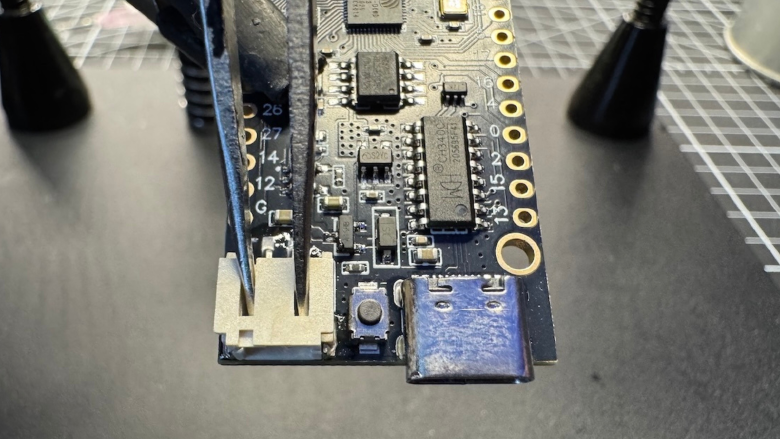
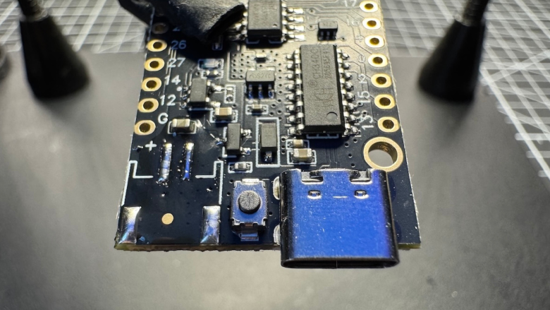
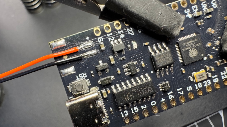
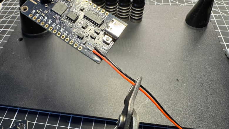
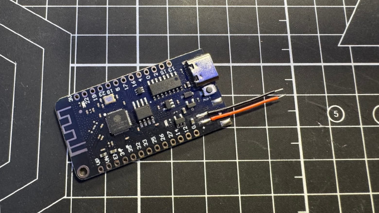
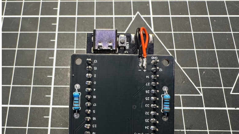
ESP32 board preparation
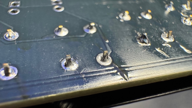
Modify the ESP32 board by removing the original JST connector and soldering the provided cable directly to the pads.
- Secure the board firmly (stand or clamps)
- Preheat your soldering iron to ~350–380°C (lead-free solder requires higher temperature)
- Apply flux before heating
- Gently pry the connector with tweezers while heating the pads — use minimal force and let heat do most of the work
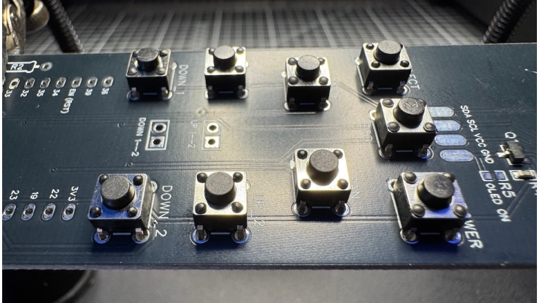
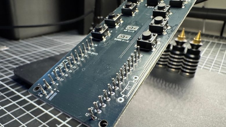
Button soldering
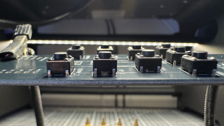
- Insert all switches from the bottom side of the PCB
- Align them evenly before soldering
- Solder one pin per switch first, verify alignment, then complete the remaining pins
- Keep solder joints small and clean
Accurate alignment is important - uneven buttons will affect both feel and enclosure fit.
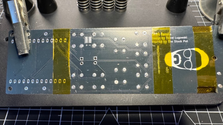
Final PCB assembly
At this stage, all individual components are ready. Now it’s time to complete the PCB and prepare it for installation into the enclosure.
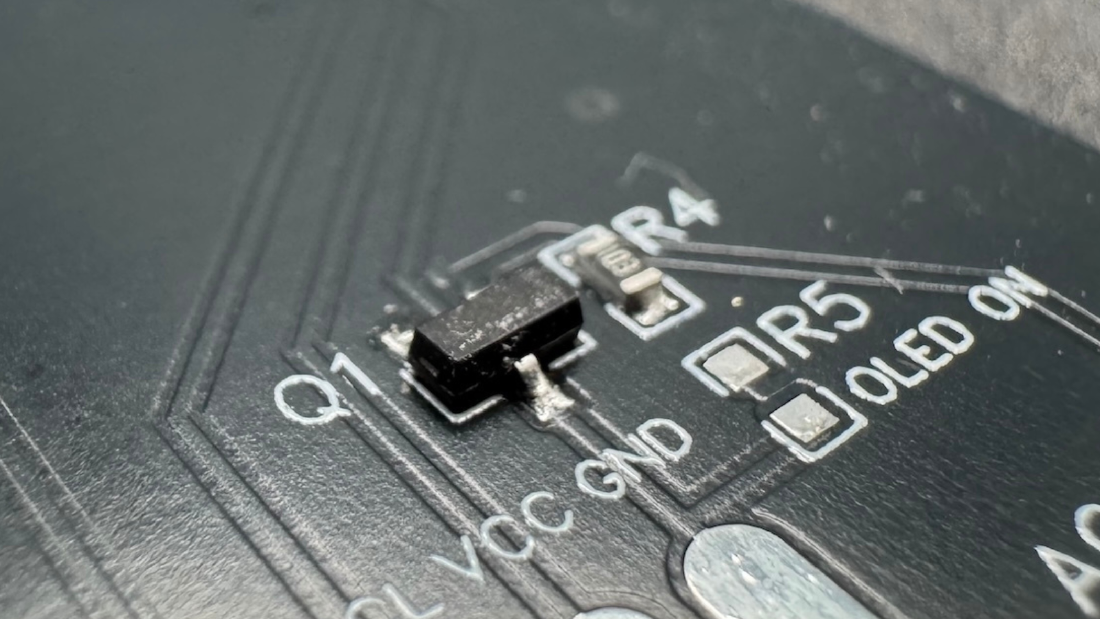
Start by checking what is already pre-soldered on your board:
- MOSFET and pull-down resistor are already installed
- remaining components need to be added manually
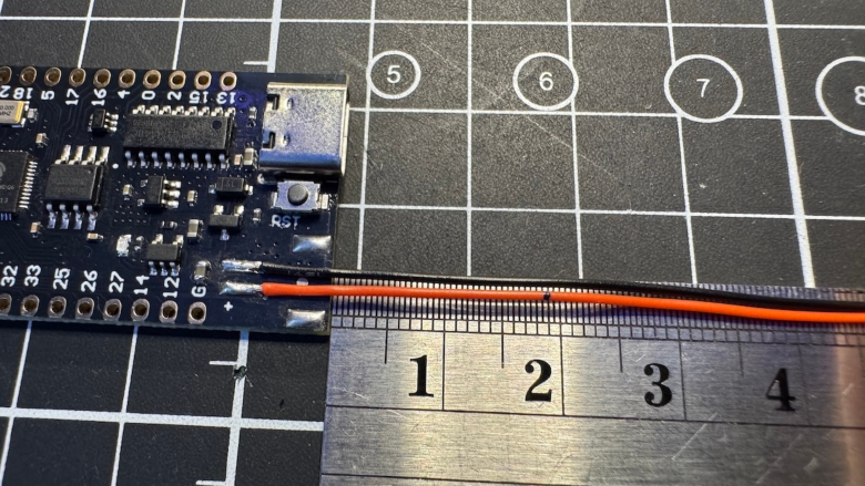
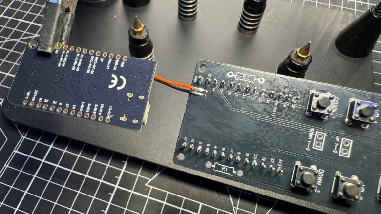
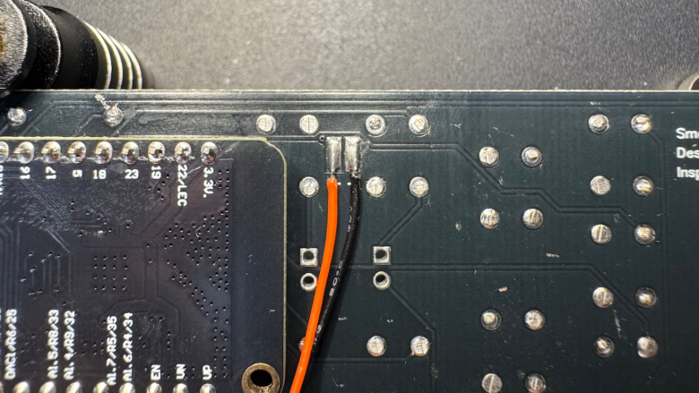
Add wires to the pads remaining after desoldering original jst connector.
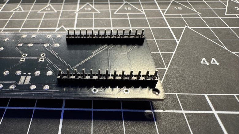
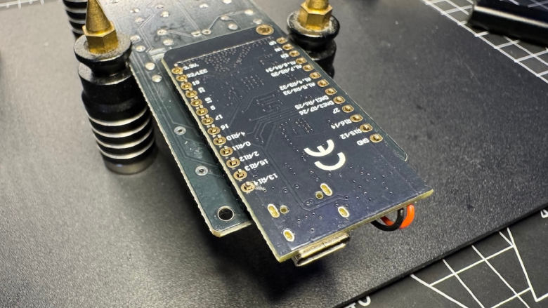
Place the ESP32 dev board onto the PCB:
- make sure all pins are aligned correctly
- verify the board sits flat before soldering
- solder a few corner pins first, then complete the rest
- ensure correct values and placement
- keep solder joints small and clean
- avoid overheating pads
Once the ESP32 is secured, connect the battery input:
- solder battery wires to the correct pads (VCC / GND)
- double-check polarity before soldering
- keep wires short and neatly routed
Before moving to enclosure assembly, perform a quick visual inspection:
- no cold solder joints
- no bridges between pins
- all components properly seated
At this point, the PCB should be fully assembled and ready to be installed into the enclosure.
Enclosure assembly
This stage focuses on placing all components into the enclosure and ensuring everything fits correctly.
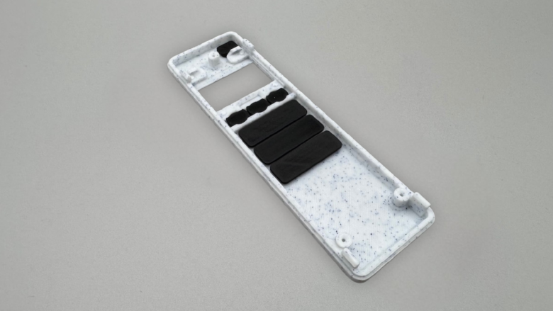
Place all button caps into the front shell.
- ensure each button moves freely
- check for any friction or sticking
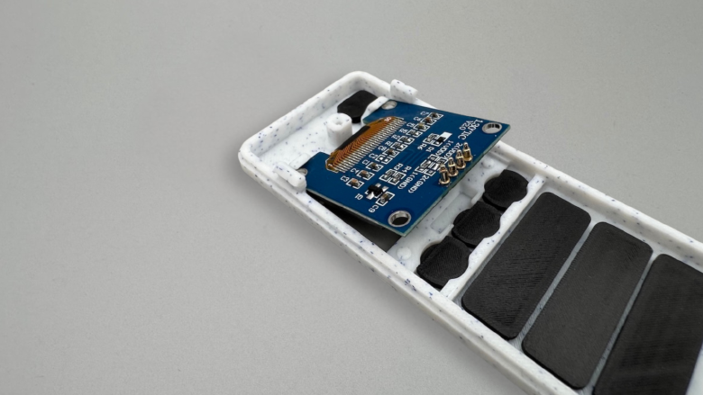
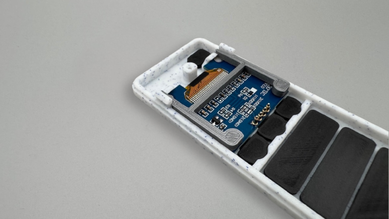
Insert the display at an angle, then press it gently into place until fully seated.
- align pins with pogo contacts
- ensure the display sits flush and stable
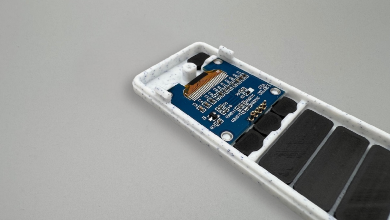
Install the support piece to secure the display to prevent movement and ensures consistent pogo pin contact.
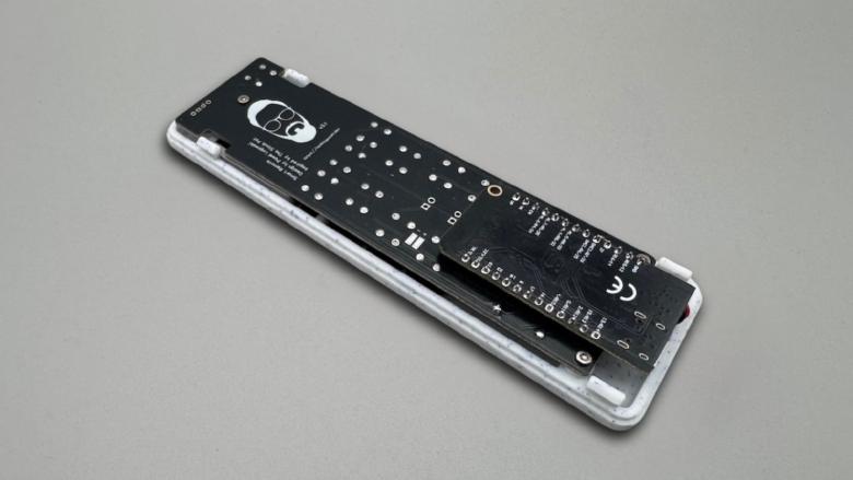
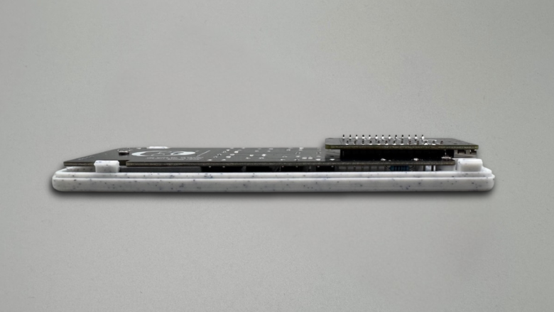
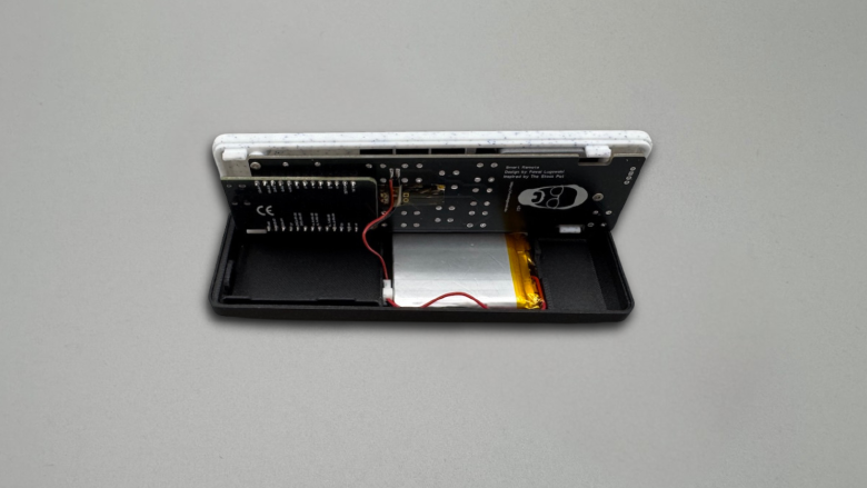
Place the PCB into the enclosure.
- pogo pins must align with OLED pads
- use side gaps to visually confirm contact
- PCB should sit flat without tension
- Secure the PCB to the enclosure using 3x M2.5 x 8 mm screws
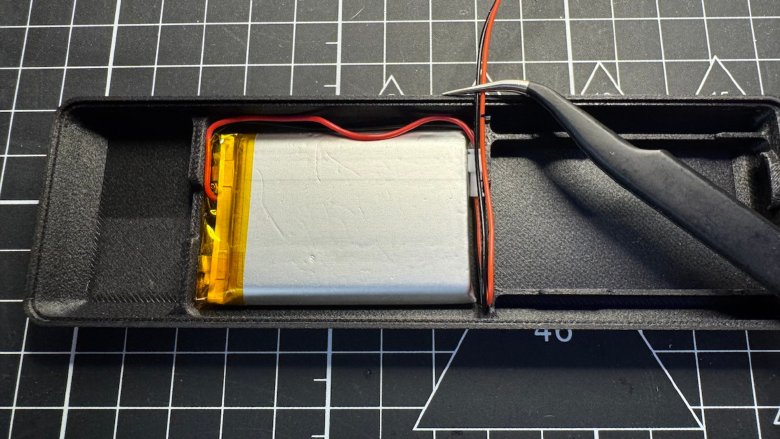
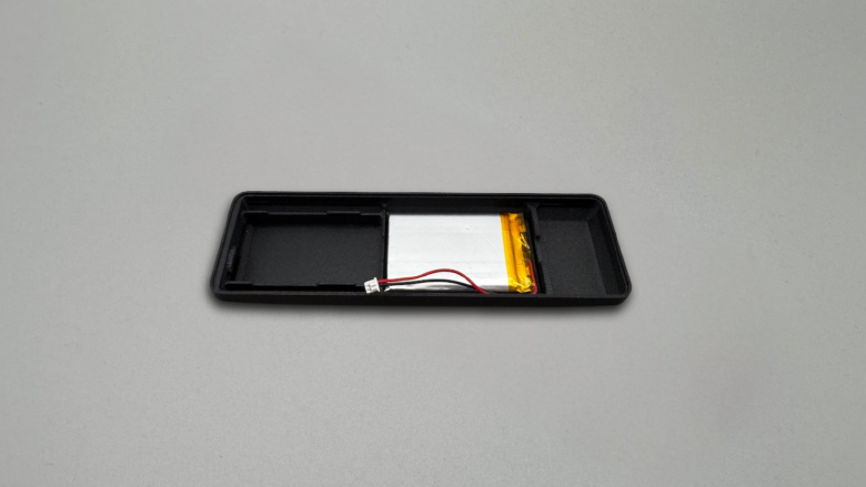
Place the battery into its compartment.
- route wires carefully
- avoid crossing or pinching cables
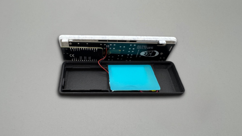
Insert the divider plate above the battery to protect the cell and keeps wiring organized.
Snap the enclosure together.
- apply even pressure
- ensure all clips are engaged
- do not force misaligned parts
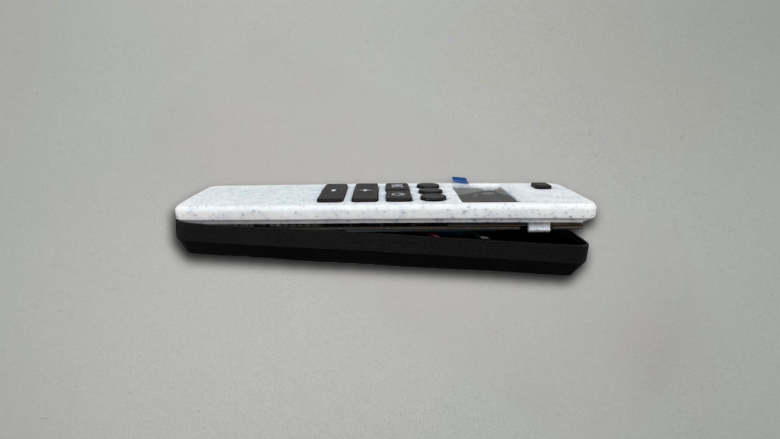
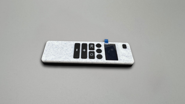
Final result
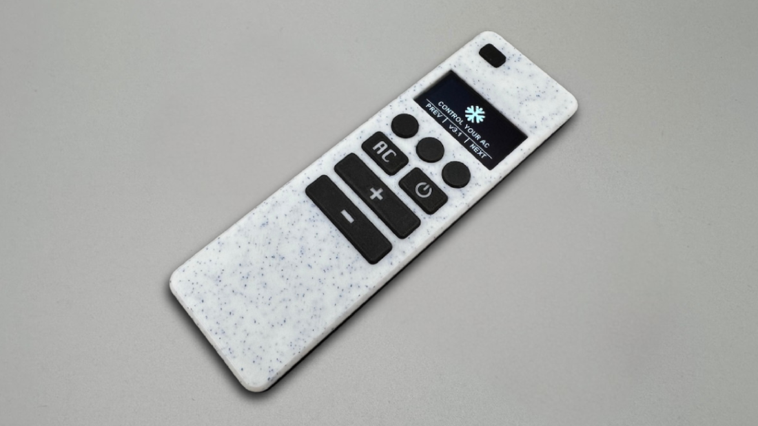
Now your remote is ready for firmware.