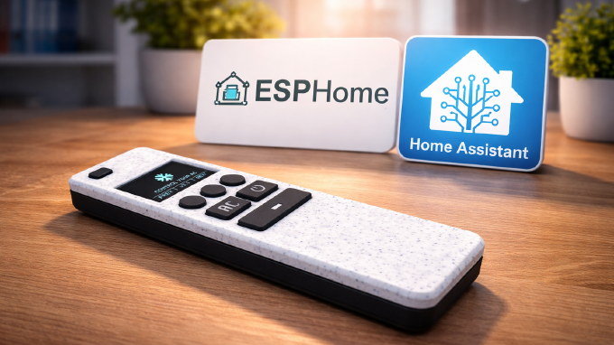
Overview
This guide covers all hardware aspects of the Smart OLED Remote, including the enclosure design, PCB, electronics, pinout, and power system.
If you’re building the device yourself or want to understand how it works, this is your reference.
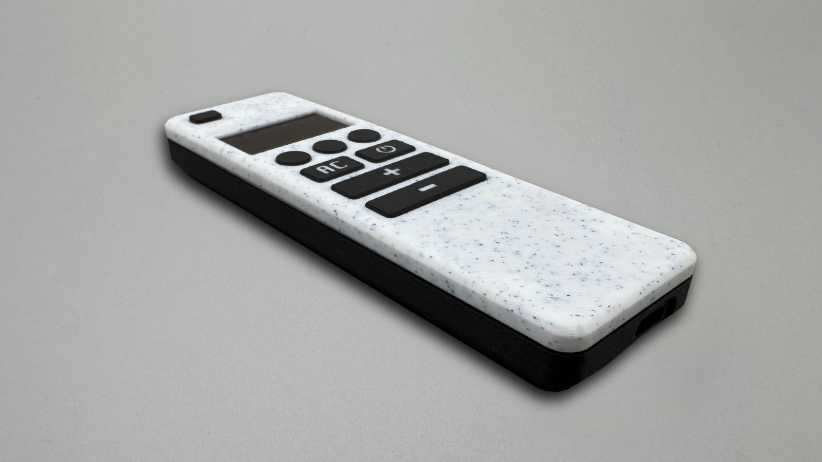
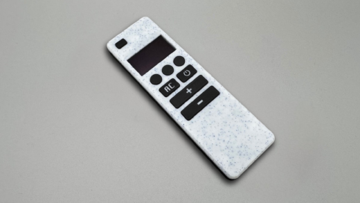
Enclosure Design
The enclosure was inspired by The Stock Pot design, but fully redesigned from scratch to better fit this project.
The main goals were:
- ensure the OLED display sits perfectly aligned
- make all buttons easily accessible with the thumb
- keep a clean, symmetrical look without visible misalignment or uneven gaps
- design the enclosure without screws, using a reliable snap-fit mechanism
Aesthetics were as important as functionality. The final result is a compact, balanced design that feels natural in hand and consistent from every angle.
Designing process
I started by carefully measuring all components and creating simple 3D reference models of the OLED display, ESP32 development boards, and tactile switches. This made it much easier to experiment with layout and positioning early in the process.
From there, I iterated on the internal arrangement to minimize overall size while keeping the device comfortable to use. I adjusted orientation for better ergonomics, added proper tolerances, and designed mounting features to hold everything securely in place.
Several prototype iterations were printed along the way. Each revision helped refine key details such as display fit, button feel and alignment, and internal spacing, until the design reached a consistent and reliable final form.
After several revisions, the design reached a stable and reliable final form.
Development board choice
I initially experimented with different ESP32 development boards. One of the first choices was the Seeduino, mainly because it allowed the USB-C port to be perfectly centered in the enclosure. From a mechanical perspective, that solution worked really well and resulted in a very clean layout.
Unfortunately, the Seeduino has limitations when it comes to the number of available GPIO pins, which became a constraint for this project.
In the end, I decided to go with the same board used in the original design — the ESP32 Lolin32 Lite V1. It is significantly cheaper, easier to source in larger quantities, and better suited for repeatable builds. Since I already had several of them available, it made sense to standardize the design around this board.
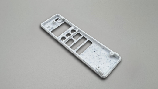
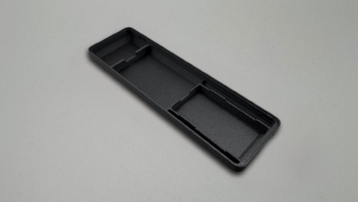
3D-Printed Parts Overview
Enclosure overview
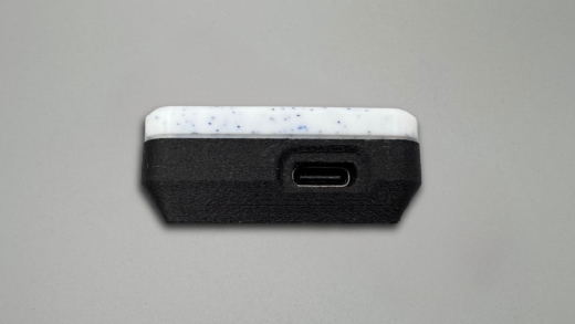
The enclosure is fully 3D printed and designed for easy assembly.
Enclosure Components
Print Recommendations
- Recommended materials: PETG or PLA. For a premium finish, carbon- or glass-fiber filaments work especially well and give a very clean look.
- For button caps with icons or labels, use a 0.2 mm nozzle - larger nozzles won’t produce sharp details.
- Ensure proper printer calibration. The enclosure uses a snap-fit design, so accurate tolerances are important for correct assembly.
- For the best surface finish, use a smooth build plate.
- No supports are required.
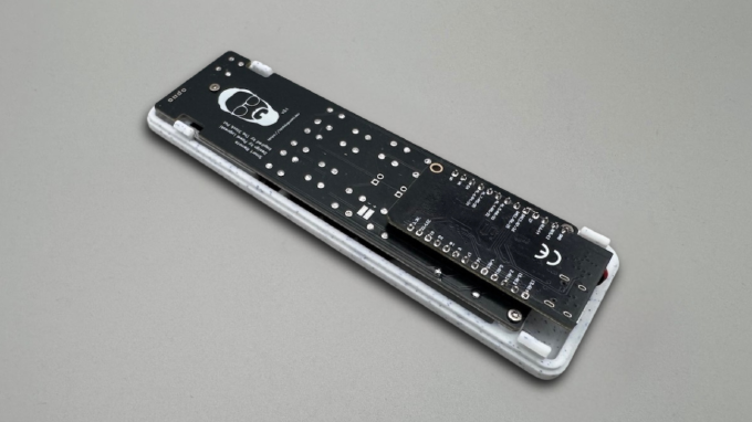
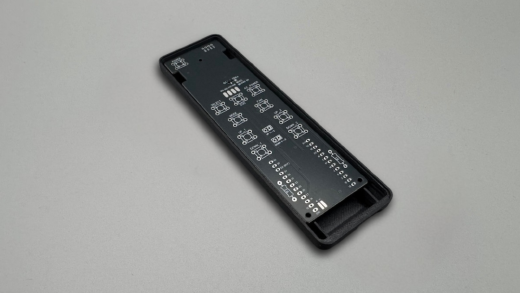
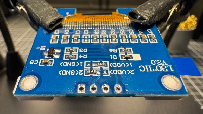
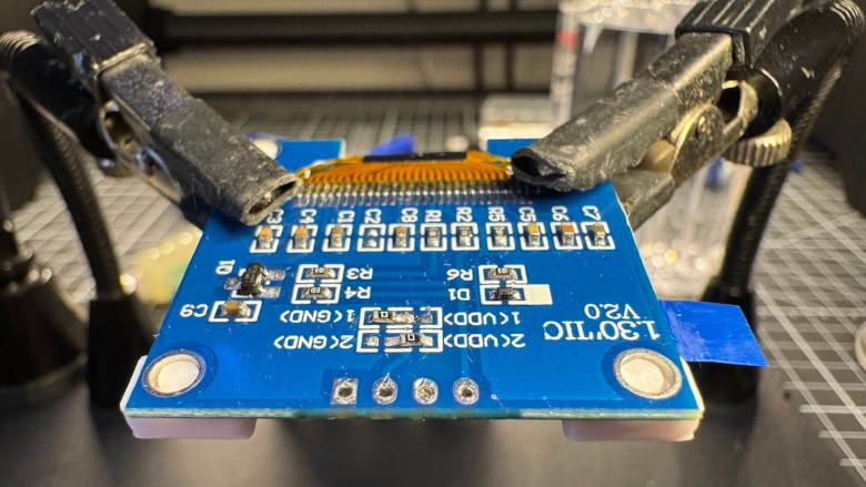
PCB Design & Versions
The custom PCB is designed to fit precisely inside the enclosure and align with all buttons and pins.
PCB Development Process
The PCB went through several iterations before reaching a stable and reliable design.
The first revision exposed a few practical issues. Some connections were missing or incorrectly routed, which required manual fixes and made assembly less predictable. It was a good starting point, but far from production-ready.
In one of the early revisions, I also routed the voltage divider trace through a breakable section of the PCB. The idea was to support multiple ESP32 development boards using optional jumpers. In practice, this created problems where the voltage divider would not behave correctly without additional modifications.
Each revision focused on fixing these issues and simplifying the design:
- correcting missing or incorrect connections
- improving routing for reliability
- removing unnecessary flexibility that introduced failure points
- optimizing layout for the final chosen board
Because every iteration required ordering and testing physical PCBs, the process took significantly more time than expected. However, this was necessary to validate real-world fit, tolerances, and electrical behavior.
Pinout & Button Mapping
| Function | GPIO |
|---|---|
| Power | 0 |
| Left Circle | 22 |
| Mid Circle | 5 |
| Right Circle | 33 |
| Left Rectangle | 14 |
| Light Rectangle | 26 |
| Long Btn 1 (L | R) | 23 | 17 |
| Long Btn 2 (L | R) | 19 | 18 |
| SDA | 27 |
| SCL | 25 |
| OLED ON/OFF | 15 |
| Voltage Divider | 32 |
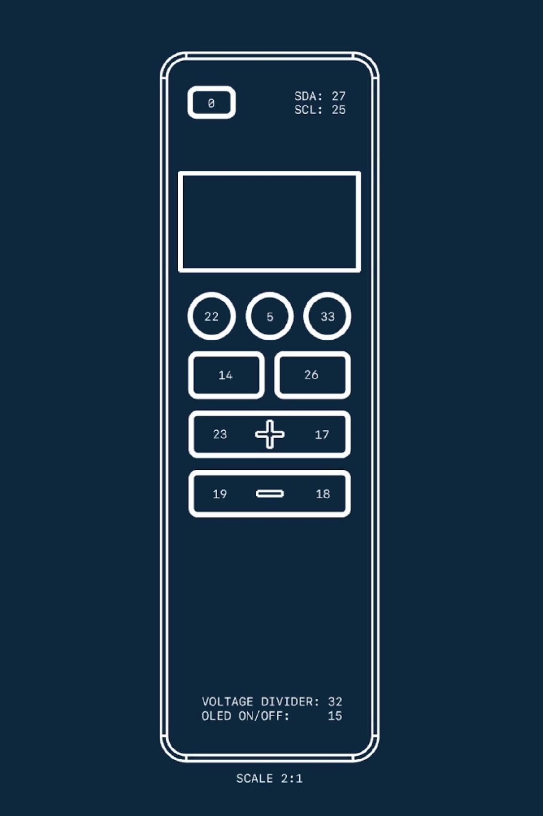
Use this table together with the annotated image to verify your wiring and configuration, especially if you are working with different PCB revisions.
Hardware Challenges
Designing this device involved several practical challenges that influenced the final hardware decisions.
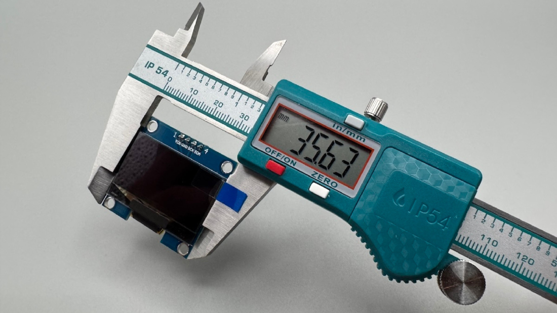
OLED connection
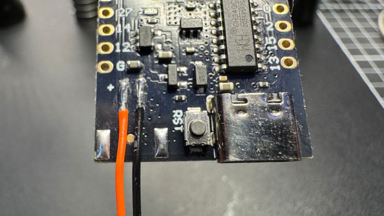
Initially, the display was connected using wires. While functional, this approach was not reliable or clean enough for a compact device.
In the final design, this was replaced with pogo pins, which:
- simplify assembly
- improve reliability
- eliminate manual wiring
Most OLED modules require resoldering their header pins to make them compatible with pogo pin contacts.
Another issue is that not all “1.3" SH1106” displays are identical:
- dimensions may slightly differ
- pin order can vary (especially GND / VCC swapped)
Because of this, always double-check pinout and fit before final assembly.
ESP32 dev board modification
To fit the ESP32 board inside the enclosure, the original battery connector must be removed and replaced with a direct cable connection.
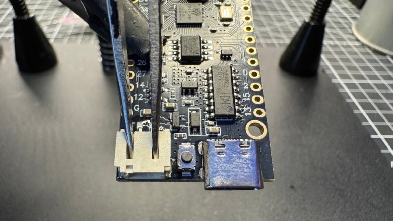
Desoldering this connector can be tricky:
- pads can be easily damaged
- too much force or heat may lift traces
Proper use of flux and controlled heat is strongly recommended.
Power consumption and OLED control
One of the less obvious issues was the OLED display itself.
Even when the ESP32 entered deep sleep, the display continued to draw current, significantly reducing battery life.
This was solved by introducing:
- a MOSFET power switch
- a pull-down resistor
This ensures the display is automatically powered off whenever the ESP enters deep sleep.
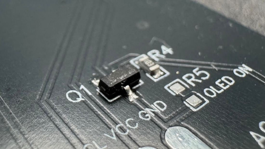
For flexibility, the PCB also includes a jumper:
- allows keeping OLED powered permanently if desired
- useful for debugging or simpler setups
However, for battery-powered use, disabling OLED power is strongly recommended.