Quick Start Guide
Thank you for purchasing the Smart OLED Remote Kit.
I truly appreciate your support - it means a lot to me that this project has found its way to you. Every purchase helps me continue improving this device and developing new ideas, tools, and projects for the maker community.
This kit contains all the essential components to build your own ESPHome-powered smart remote.
TL;DR
You’re all set - follow the Assembly Guide and start building your remote.
Kit Contents
| Part Symbol | Description | Qty |
|---|---|---|
| PCB | Custom designed PCB | x1 |
| ESP32_DEVKIT_LOLIN_V1 | Main microcontroller | x1 |
| OLED_SH1106_I2C_128x64 | OLED Display 1.3" | x1 |
| JST 1.25 2P | Wired connector for battery | x1 |
| POGO_4MM_PTH | Pogo pins for OLED | x4 |
| RES_6K8_TH_0.25W | 6.8 kΩ for voltage divider | x1 |
| RES_10K_TH_0.25W | 10 kΩ for voltage divider | x1 |
| SW_TACT_6x6x5_TH | Tactile push buttons | x10 |
Battery Information
Due to international shipping restrictions, small sellers like me cannot send products containing lithium batteries. That’s why the battery is not included, as mentioned in the store description.
You can easily buy a suitable battery on AliExpress, Shopee, or local electronics stores.
| Type | Li-Po / Li-Ion |
|---|---|
| Size | 603450 |
| Connector | JST 1.25 mm (micro JST) |
| Example | AliExpress |
OLED Display
Some OLED displays may arrive with different pin orders depending on the supplier.
Please check the pin order printed on the display before soldering. If pins are labeled VDD, GND, SCK, SDA, you need to resolder two resistors on the back of the display board to swap the first two pins (VDD ↔ GND).
After checking the display pin order, first remove the pre-soldered header pins from the OLED module for better access to resistors.
Once you’ve swapped the resistors, install the pogo pins from your kit where the original header pins were to ensure a solid connection with the PCB.
PCB Board
Your PCB may vary slightly depending on the version, as the design is continuously being improved. The version is printed directly on the board (available from v3 onward). If it’s not present, refer to the table below to identify your PCB based on layout differences.
Version Highlights
- v1 – Original version. No pogo pin pads; OLED required a Grove connector.
- v2 – Added pogo pin pads, I²C expansion, voltage divider resistors, jumpers, and optional Seeduino XIAO ESP32 support.
- v3 – Reorganized GPIO layout, added MOSFET for OLED power control and fixed pads to connect battery positive terminal to voltage divider.
PCB Version Differences
| Function | v1 | v2 | v3.1 |
|---|---|---|---|
| Power | 0 | 0 | 0 |
| Left Circle | 22 | 22 | 22 |
| Mid Circle | 32 | 32 | 5 |
| Right Circle | 33 | 33 | 33 |
| Left Rectangle | 14 | 14 | 14 |
| Light Rectangle | 26 | 26 | 26 |
| Long Btn 1 (L | R) | 23 | 5 | 23 | 12 | 23 | 17 |
| Long Btn 2 (L | R) | 19 | 18 | 19 | 18 | 19 | 18 |
| SDA | 27 | 27 | 27 |
| SCL | 25 | 25 | 25 |
| OLED ON/OFF | X | X | 15 |
| Voltage Divider | X | 36 | 32 |
| Battery pads (bottom) | — | Y | Y |
| Battery pads (both sides) | — | — | Y |
| PCB | 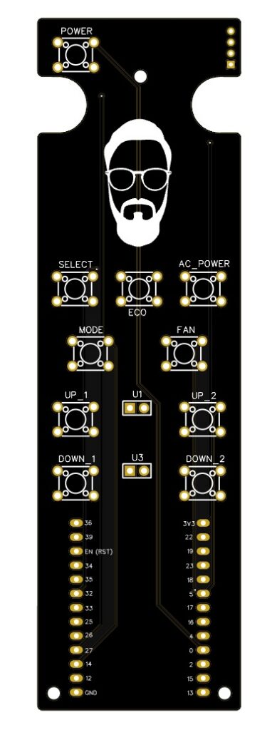 | 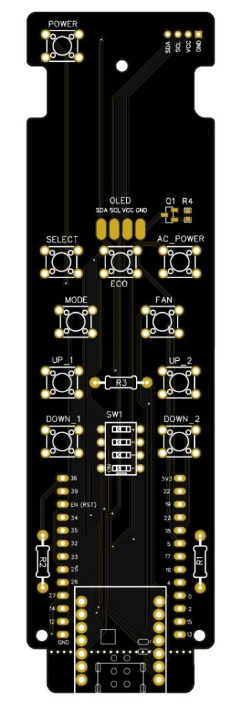 | 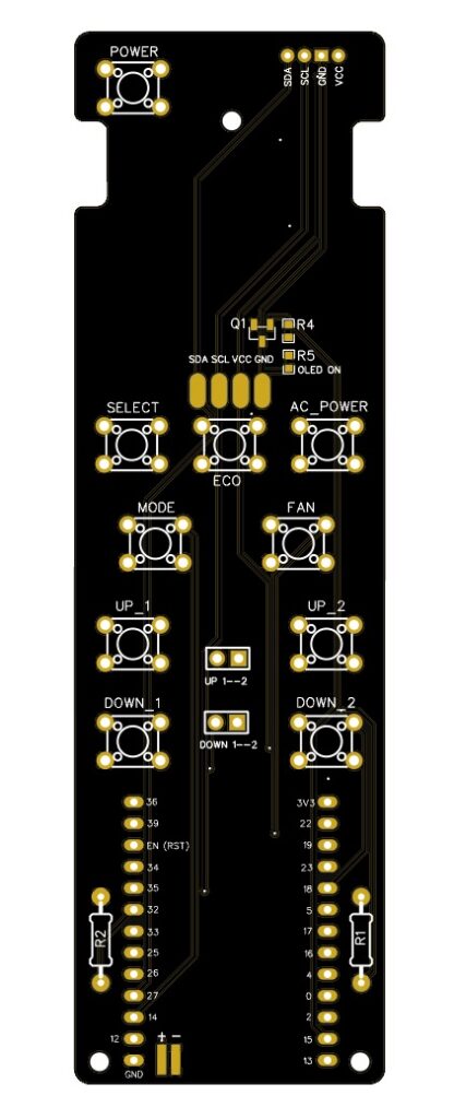 |
Tactile Switches
All switches should be soldered from the bottom side of the PCB.
- Place all 10 switches and align them before soldering.
- Tack one pin per switch, confirm alignment, then complete the remaining joints.
- Keep the PCB flat during soldering to ensure proper seating of the switches.
- Apply minimal solder for clean, low-profile joints.
- Limit heat exposure to ~1–2 seconds per pad to avoid damage.
- After soldering, trim the switch leads to maintain a flat surface and prevent contact with the battery.
Resistors
Solder the included resistors in their corresponding slots on the PCB.
- R1 – 6.8 kΩ (1%) → blue-gray-black-brown-brown
- R2 – 10 kΩ (1%) → brown-black-black-red-brown
ESP32 LOLIN32 Board Modification
Before installing the LOLIN32 Lite board, a small modification is required to prepare it for the battery connection.
Carefully desolder the original JST connector from the board.
- Apply flux to the solder joints and mounting tabs.
- Heat the pins while gently lifting the connector.
- Avoid excessive force to prevent damaging the pads.
Trim the battery cable to approximately 7–8 cm.
Take the provided cable with a JST-1.25 connector and solder it to the same pads on the board:
- Red wire → positive (+)
- Black wire → negative (–)
Power & Connections
- Connect the LiPo battery using the provided JST connector.
- A built-in voltage divider allows battery voltage monitoring in ESPHome.
- OLED power is switched via a MOSFET on GPIO15 — it must be enabled in YAML before display initialization (available from PCB v3).
Next Steps
After assembly, follow the guide to re-flash the device and connect it to your Home Assistant instance.
Once everything is working, you can build your own YAML configuration based on the examples available on my GitHub, or use the Tools section where I’ve prepared a user-friendly YAML generator for this project.
Thank you
… one more time and I hope you enjoy using it as much as I enjoyed building it.