ESP32 · Home Automation · 3D Printing
Build it yourself
or skip ahead.
ESP32, Home Assistant, and custom hardware projects with practical guides and real results.
// featured projects
Featured Projects

// recently published
Latest Guides

Smart OLED Remote ESPHome Setup and Configuration
Flash firmware, connect the Smart OLED Remote to Home Assistant, and understand how the configuration is structured.
Smart OLED Remote – Assembly Guide
Step-by-step instructions to assemble the Smart OLED Remote, including soldering, display installation, and final enclosure assembly.

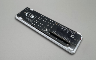
Smart OLED Remote – Hardware & Design Guide
Detailed overview of PCB, electronics, pinout, and 3D-printed enclosure for the Smart OLED Remote.
// about
Hi, I'm Paweł.
Software engineer by day, maker by night. I write practical guides and build open-source projects around ESP32, ESPHome, Home Assistant, and 3D printing.
This site is where I share what actually works - real parts, real builds, no filler. When I'm not soldering, I'm usually on an electric skateboard or watching a print at 2 AM.