This article is part 2 of the Smart OLED Remote for Home Assistant series.
In this post, we’ll look closer at what makes the remote work — its ESP32 Lolin32 WROOM board, custom PCB pinout, voltage divider for battery measurement, and the SH1106 OLED display that brings everything to life.
Smart OLED Remote Series
- Part 1 – Overview & Features
- Part 2 – PCB, OLED & Electronics (you are here)
- Part 3 – Assembly Guide
- Part 4 – ESPHome Firmware
The Core: WROOM Lolin32 Lite V1.0
At the heart of the remote is a Wemos Lolin32 development board based on the ESP32-WROOM-32 module.
It’s compact, easy to mount, and provides all the features needed for a low-power, Wi-Fi–connected handheld device. In this project, the Lolin32’s 3.3 V rail powers the OLED display and voltage divider.
The board’s built-in LiPo charger makes it ideal for portable use — just connect a small LiPo battery and the device can charge over USB.
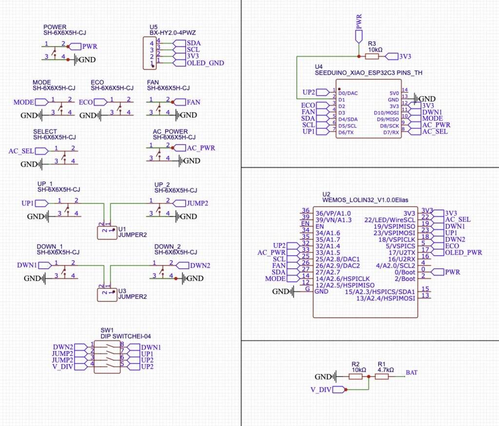
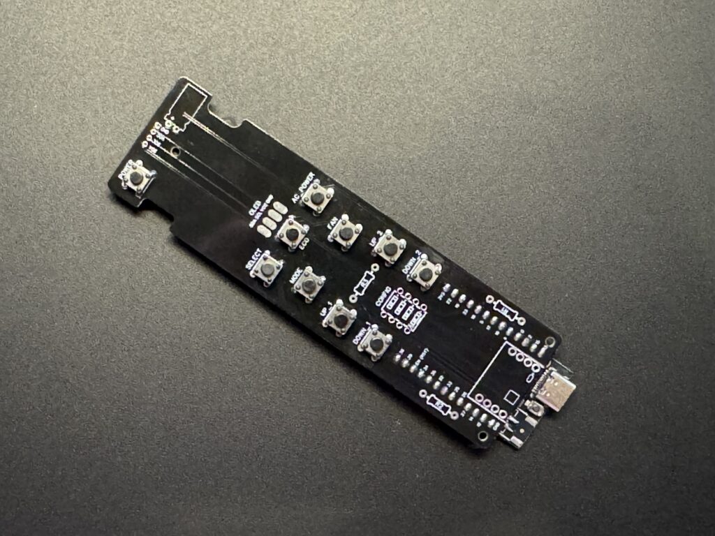
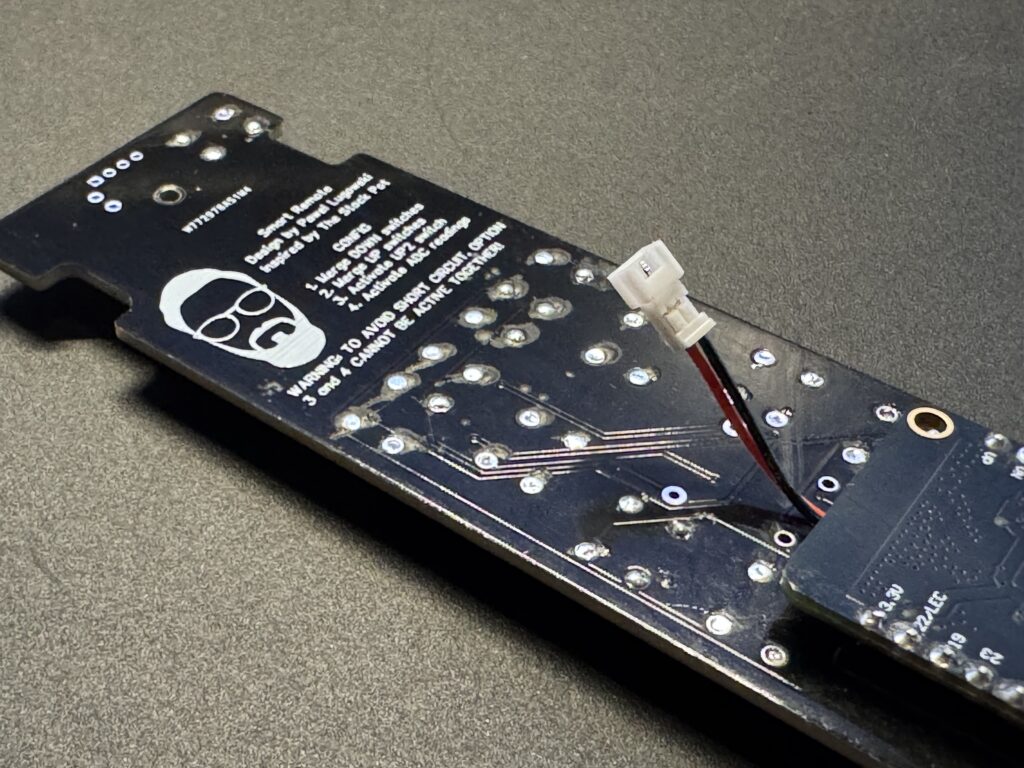
PCB Pinout
The custom PCB connects several tactile switches to dedicated GPIO pins on the ESP32 for clean digital input detection.
Each button has one side connected to GND and the other routed to a GPIO pin with an internal pull-up enabled via ESPHome.
Because the Seeduino Xiao has a limited number of available GPIO pins, not all switches on the remote can be used with that board. The Lolin WROOM board provides more flexibility.
In this design, two switches are used together to operate each of the long buttons (Temperature Up and Down). This approach minimizes wobbling when pressing the buttons and leaves the option to later redesign them as two independent buttons if additional features are needed.
Currently, the main functional buttons are those on the left side. Pressing the right side won’t trigger any action because those switches are connected to separate pins. To link both sides of each long button, the PCB includes jumpers that allow merging them:
- Jumper 3: connects UP1 and UP2
- Jumper 4: connects DOWN1 and DOWN2
Additionally:
- Jumper 1 enables the voltage divider used for battery voltage measurement on the Seeduino (the Lolin already has this connected to GPIO 36).
- Jumper 2 allows using the UP2 switch as an independent button.
Important: On the Seeduino, the voltage divider and UP2 switch share the same pin. Therefore, Jumpers 1 and 2 cannot be enabled at the same time — doing so could cause a short circuit.
Battery Voltage Sensing via Voltage Divider
To monitor the LiPo battery voltage, the PCB uses a voltage divider connected to the ESP32’s ADC pin (GPIO 36).
Since a single-cell LiPo typically ranges from 4.2 V (fully charged) down to 3.0 V (low) — higher than the ESP32’s safe ADC limit of 3.3 V — the divider scales the voltage down using two resistors: 6.8 kΩ (R1) and 10 kΩ (R2).
Vout = Vin * (R2 / (R1 + R2))

Vout = Vin * (10 / (6.8 + 10))
Vout ≈ Vin * 0.595
This means a 4.2 V battery will be measured as approximately 2.5 V at the ADC pin — well within the safe range for the ESP32.
Resistor color code (5-band):
- 6.8 kΩ (1%) → blue-gray-black-brown-brown
- 10 kΩ (1%) → brown-black-black-red-brown
These precision resistors ensure accurate, stable voltage readings and protect the ESP32 from excessive input voltage.
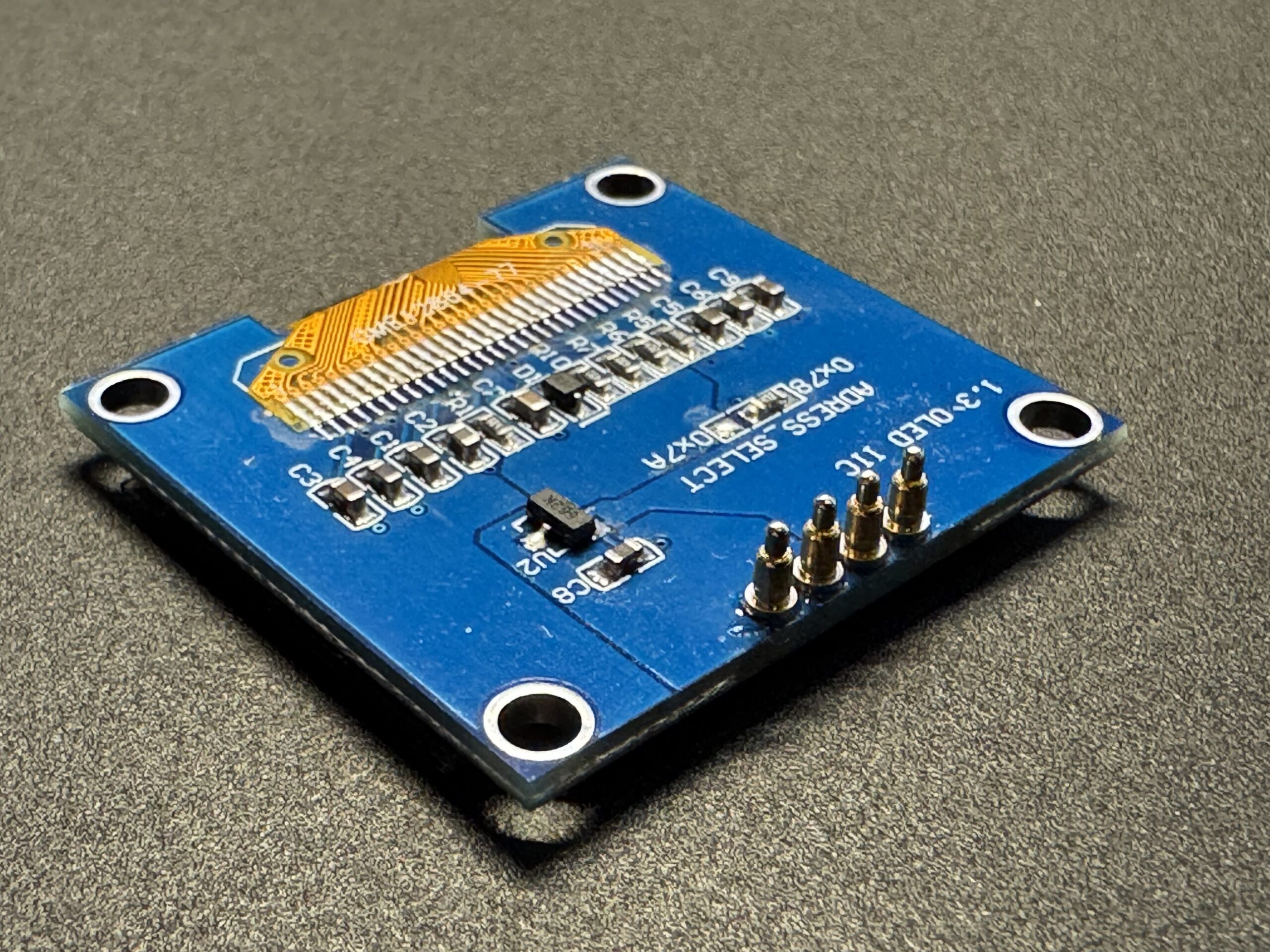
OLED Display (SH1106 1.3″)
The display used is a 1.3″ SH1106 128×64 OLED module connected over I²C. It’s similar to the more common SSD1306 but has a slightly larger addressable area and internal memory buffer.
Soldering components to PCB
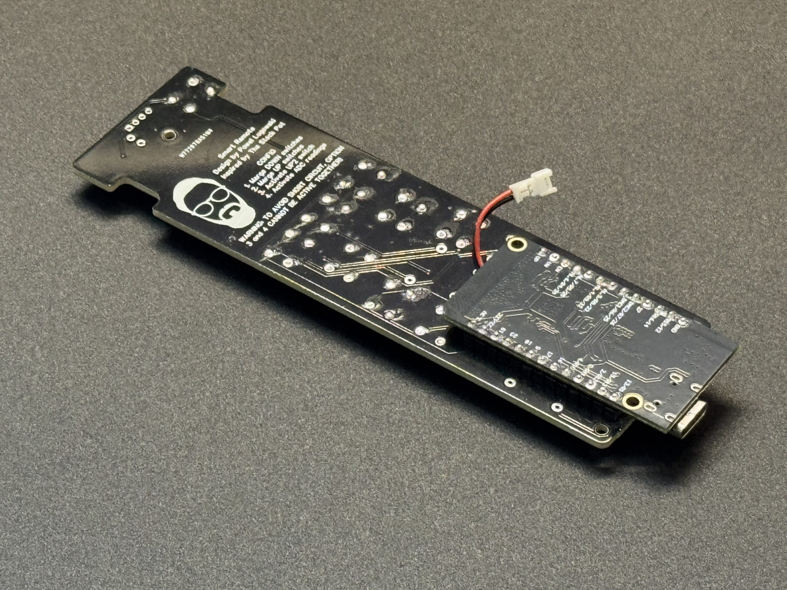
For the Lolin board, first desolder the built-in battery connector and replace it with a Micro JST cable connector, as shown in the reference image. Make sure the cable is long enough to comfortably reach the battery compartment once assembled.
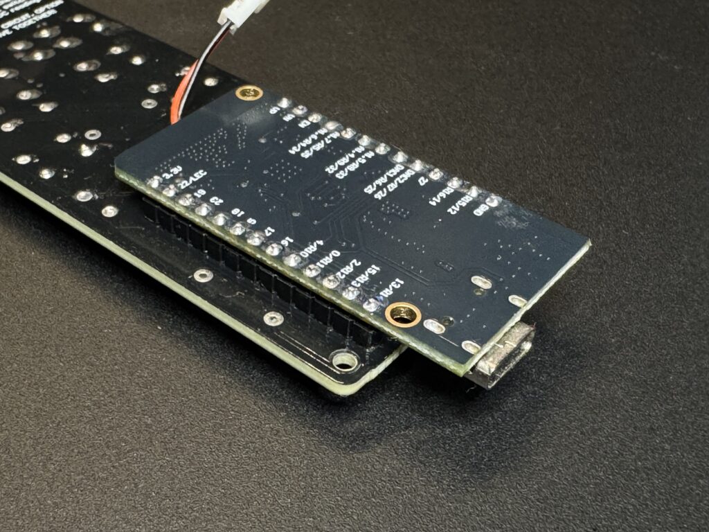
Next, mount the Lolin board upside down onto the PCB, following the orientation shown in the attached image.
Before soldering, carefully verify that all pin labels on the PCB and the Lolin board match to avoid incorrect connections or short circuits.
Solder tactile switches. Make sure that all tactile switches are properly soldered to PCB, and sharp legs are cut off.
Attach battery connector. On Lolin board remember to desolder battery connector, and solder instead of it JST 1.25mm female connector for battery, double check polarity with your battery!
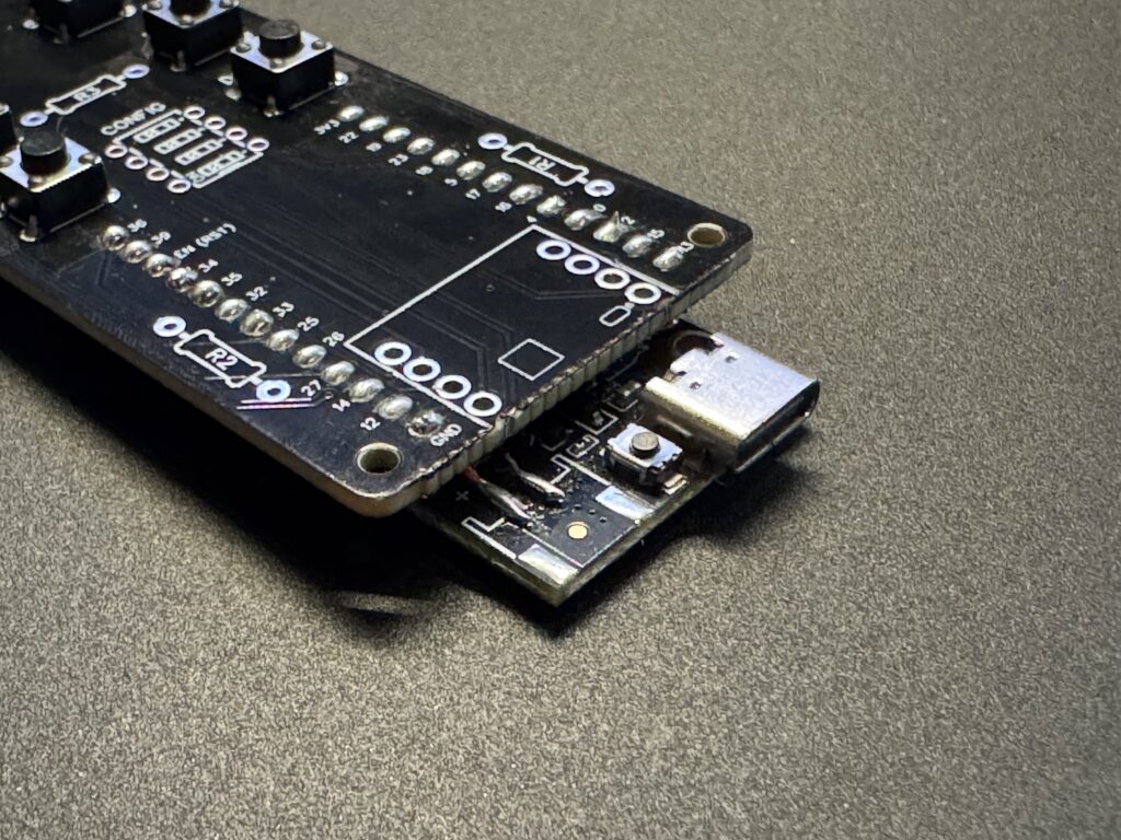
Solder devboard to PCB. PCB is compatible with both ESP32-Lolin or Seeduino ESP32, you will find proper holes for soldering on PCB itself.
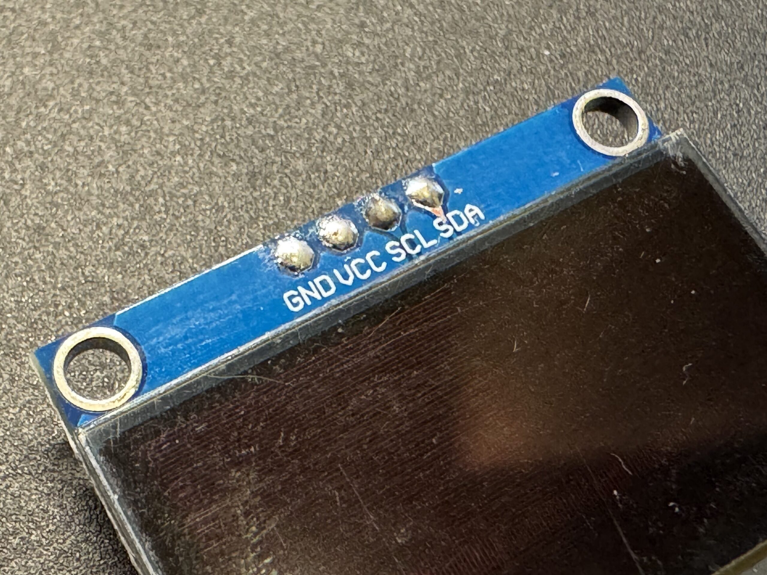
Solder POGO pins to your OLED display. Be sure that your display pins orders is GND, VCC, SCL, SDA. Some models has switched VCC and GND but it can be changed by changing jumpers on display itself.
Power Management Notes
- The Lolin32’s charging circuit manages the LiPo cell automatically.
- You can connect the battery directly to the BAT and GND pads.
- The 5 V USB input charges the battery and powers the device simultaneously.
- The voltage divider is always connected, but the 100 kΩ values keep the quiescent draw negligible (< 20 µA).
What’s Next
Now that you understand how the electronics work, it’s time to bring it all together: Part 3 – Assembly Guide →