This guide explains how to assemble the Smart OLED Remote for Home Assistant step by step. It covers mounting the PCB, installing buttons and the OLED display, connecting components, and closing the 3D-printed case.
Smart OLED Remote Series
- Part 1 – Overview & Features
- Part 2 – PCB, OLED & Electronics
- Part 3 – Remote Assembly Guide (you are here)
- Part 4 – ESPHome Firmware
What You’ll Need
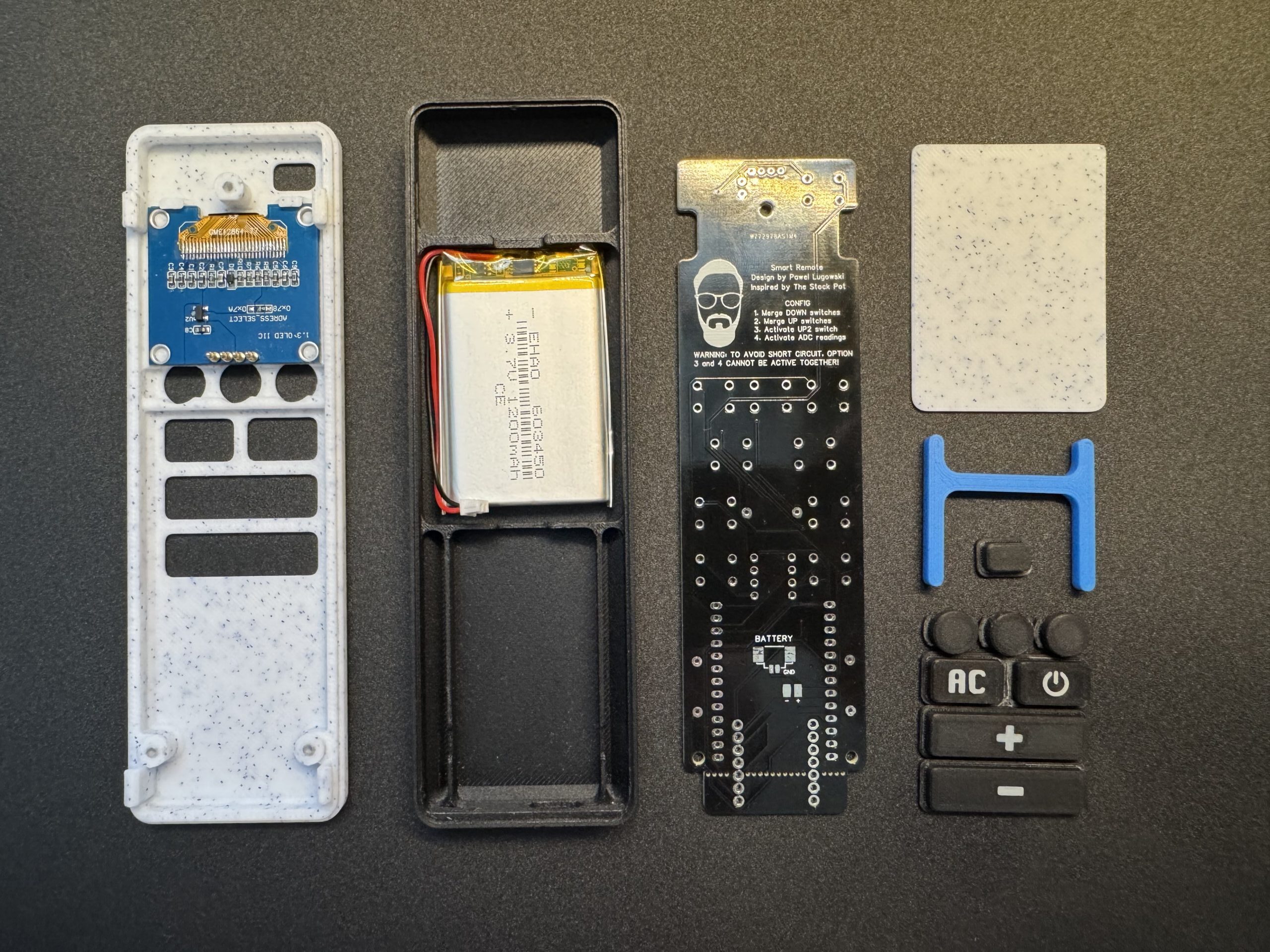
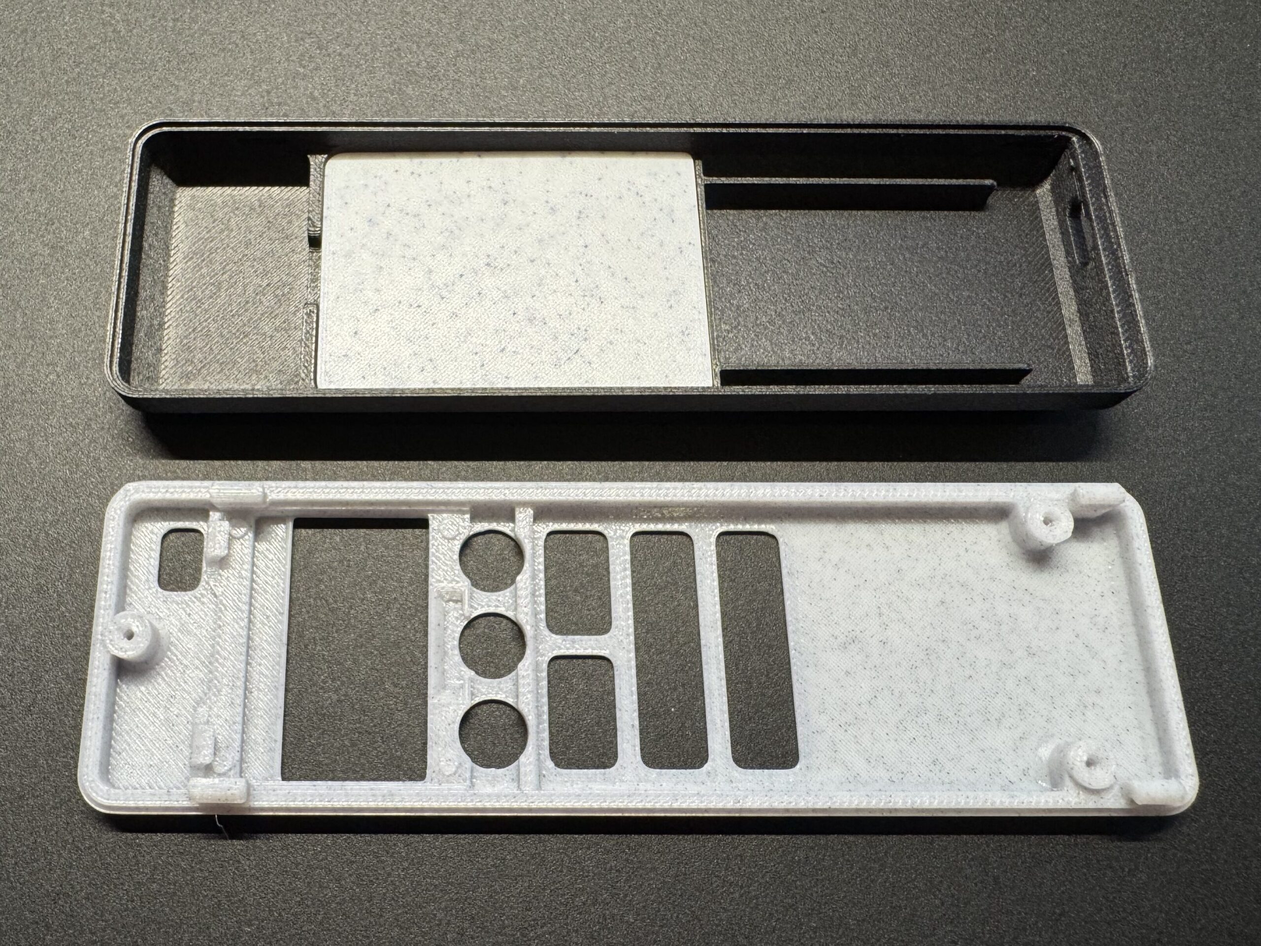
- 3D-printed enclosure (front and back cover + button caps + battery divider)
- Pre-soldered PCB with tactile switches and ESP32 board
- Li-ion battery 603450
- 3x M2.5×6 screws
Step-by-Step Assembly
Print the case. Make sure all printed parts are clean. Test-fit the clips and buttons before installing electronics. If any edges are rough, lightly sand them for smooth operation.
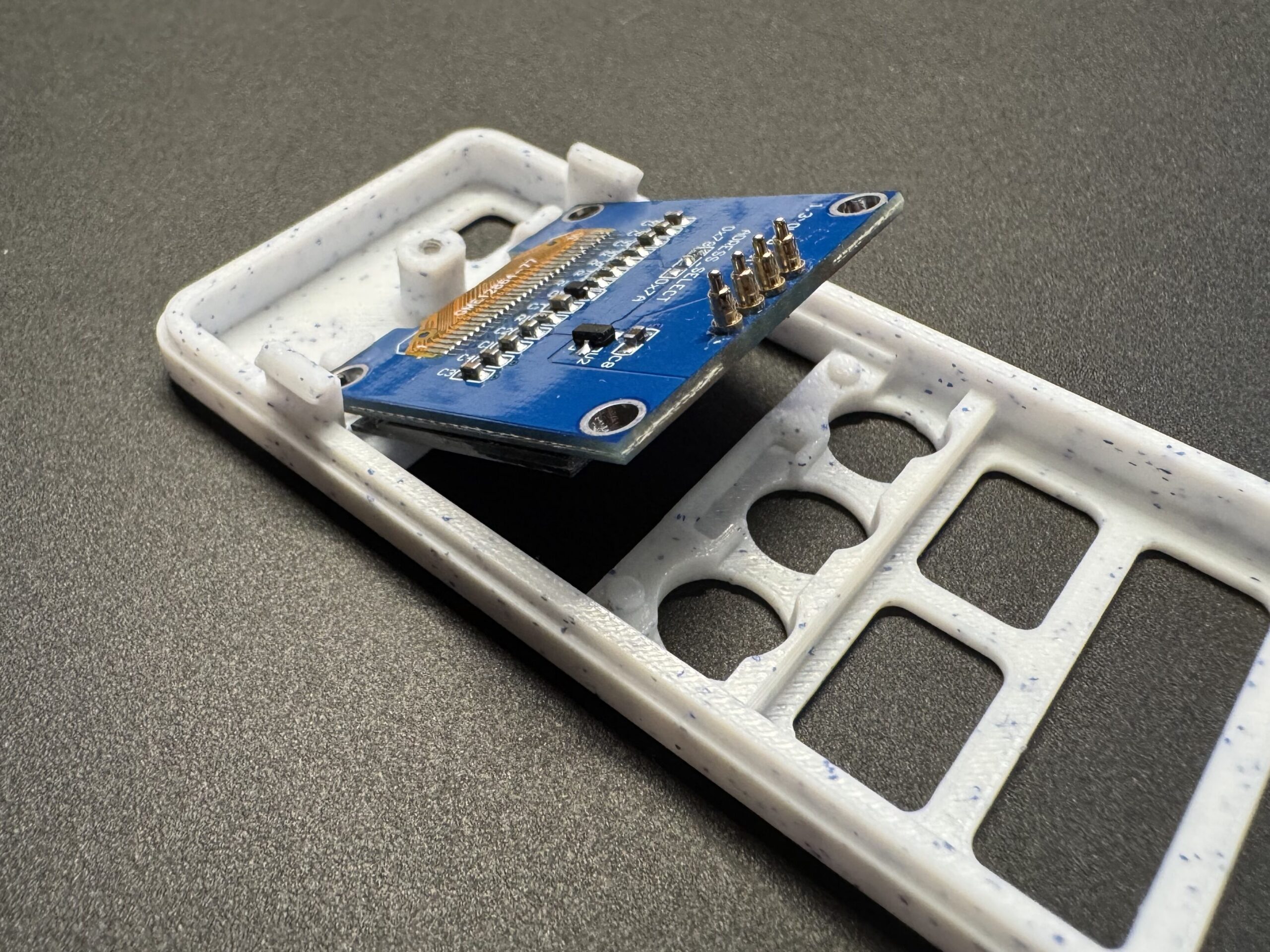
Insert the OLED display. Slide the display module into the front frame in 45 degree angle. Be careful here as display is quiet fragile and slot is really tight fit.
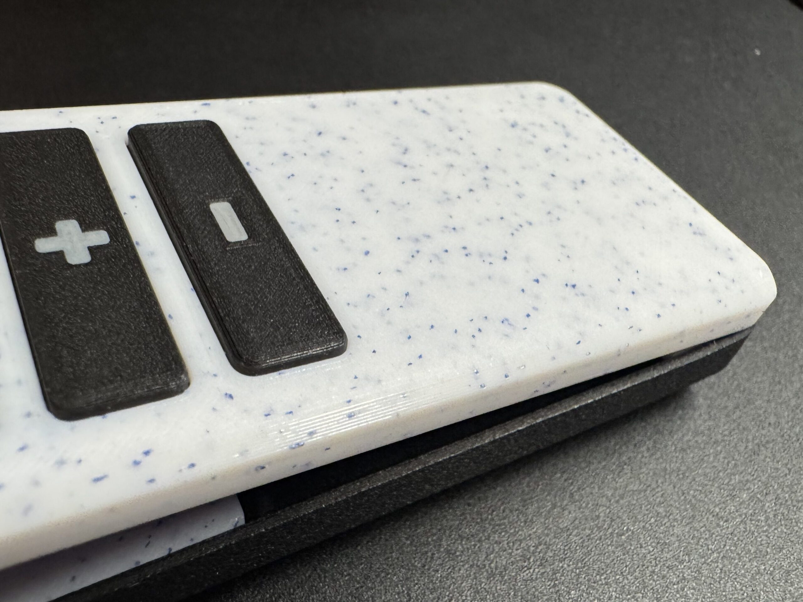
Install the buttons Insert the printed buttons caps into their respective holes from the outside. Check that they move freely but don’t fall out.
Place display in it’s final place. After placing all buttons into their proper slots, gently move the display into its final position. To do this, press it lightly from the edge and push it downward until it clicks securely into place.
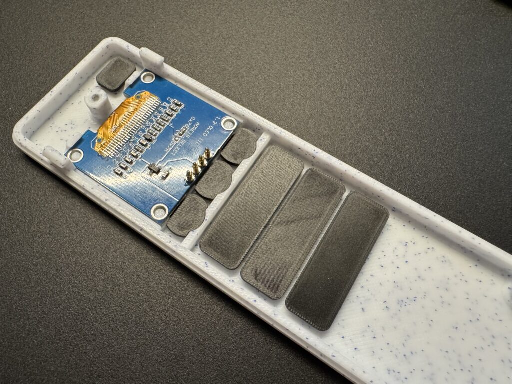
Place OLED support. A small support structure is required to ensure the display remains securely in place and doesn’t shift if external pressure is applied to the front of the case.
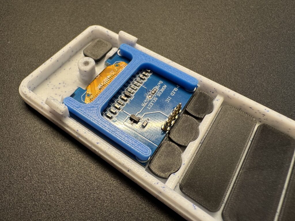
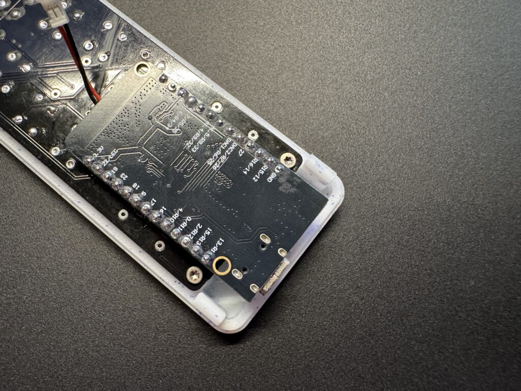
Mount the PCB and ESP32. Place the PCB into the lower half of the enclosure and secure it using three M2.5 screws. Once mounted, check that the POGO pins make firm spring contact with the PCB by visually inspecting them through the side gap.
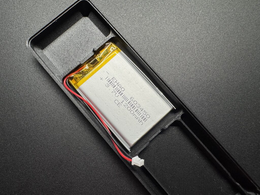
Install the battery and divider plate Place the Li-ion battery into its compartment. You can secure it using double sided tape. Insert the divider plate to separate it from the electronics, ensuring protection from pressure or puncture.
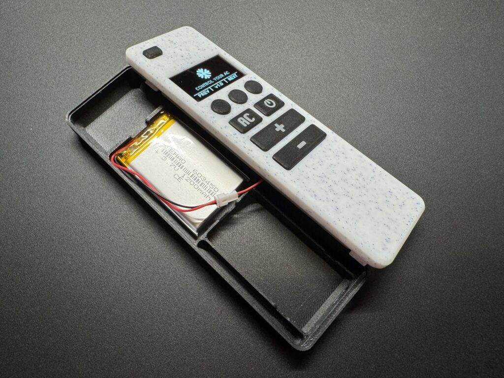
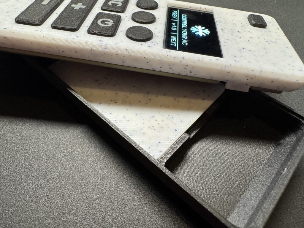
Close the enclosure Align the clips of the back cover and press gently until all sides snap into place. No screws are needed — the design locks tightly with reinforced clips. The ESP32 board should align with the USB-C cutout.
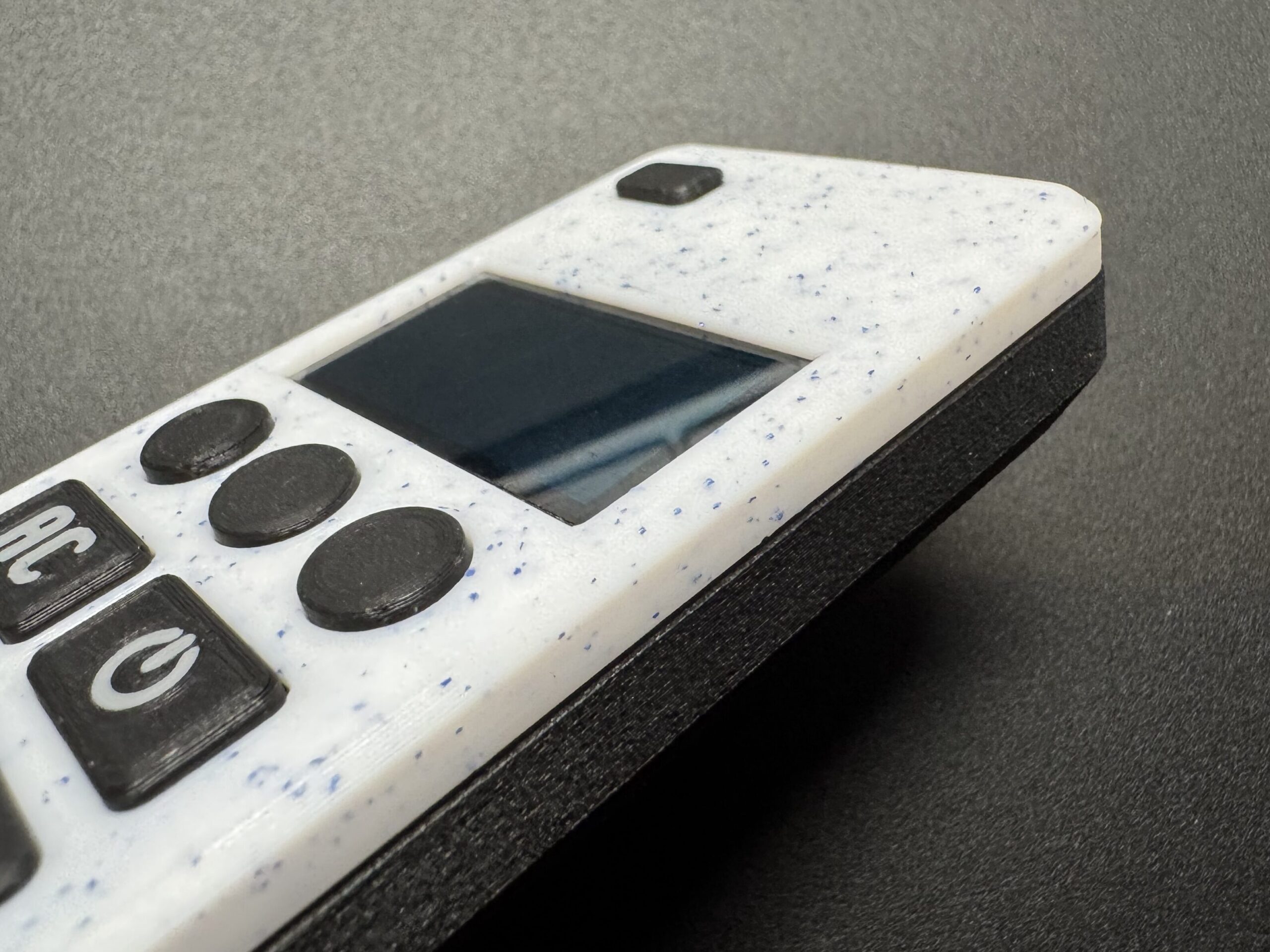
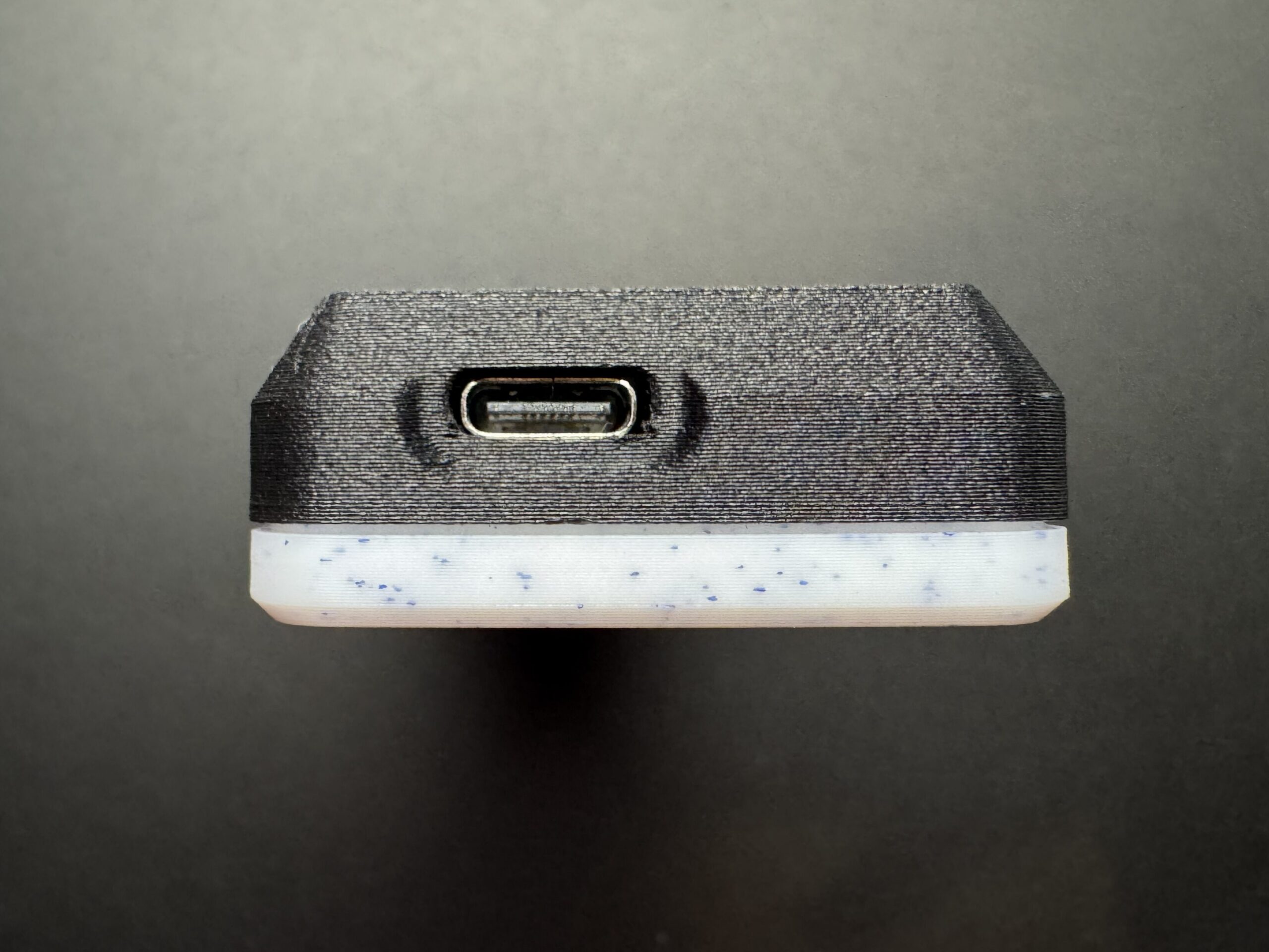
Power and test Connect a USB-C cable or wake the device from battery power. The OLED should light up and display your Home Assistant data via ESPHome.
Tips
- If the screen doesn’t light up, double-check SDA/SCL connections and OLED power polarity.
- Don’t force the clips — if alignment feels off, reopen gently and adjust.
- The case may feel tight at first but loosens slightly after a few openings.
- Use low-temperature PLA or PETG for best strength and snap-fit flexibility.
Final Check
Once assembled, your remote should:
- Power on correctly from the battery or USB-C
- Display AC state and temperature on the OLED
- Send commands to Home Assistant through ESPHome
- Sit solidly in hand without any squeaky noise
What’s Next
Now that your remote is fully assembled, it’s time to bring it to life!
In the next step you’ll learn how to flash your LOLIN32 board, configure your display and buttons, and connect the remote to Home Assistant.
Continue to Part 4 – ESPHome Firmware →